Such a supply can easily be provided on ocean-going vessels, in port, at terminals and in the shipper's and receiver's warehouses. Clip-on units may additionally be fitted to many container types, in which case they serve only to supply the refrigeration unit with electricity.
| Figure 87: Air flow in a Seacold integral container | ||||||||||||||||||||||||||||||||||||
|
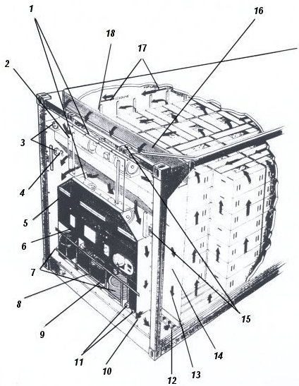
The most commonly used type of refrigerated container has an integral refrigeration unit (integral unit container). Air flow in the integral unit container is the same as that in the porthole container (see Fig. 88).
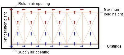 |
| Figure 88: Air flow in integral unit container The refrigeration unit blows the cold air into the lower part of the container. It is distributed over the entire container length via the gratings and rises upwards through the cargo. The air is then drawn off from the container's upper return air opening via the air channel left clear beneath the container roof and cooled in the refrigeration unit. If the maximum load height is exceeded, there is not enough space left for the air to circulate properly. |
Due to the refrigeration unit fitted onto their end face, clip-on containers are longer than integral containers, while the latter have a smaller cargo capacity. Close to the refrigeration unit, there is a ventilation flap which, depending upon its setting, allows a proportion of the circulating air to escape, so drawing fresh external air into the container (see Fig. 89).
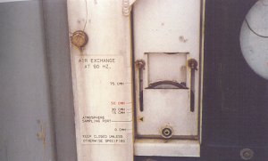 |
| Figure 89: The Figure shows the ventilation flap which can be used to control the supply of fresh air when transporting goods of vegetable origin. Since there are many different models of fresh air flaps and many different procedures for using them, the settings specified in the shipper's cooling order must always be followed to the letter. Photo: U. Schieder |
Such controlled fresh air exchange allows harmful metabolic products from goods of vegetable origin, such as carbon dioxide or ethylene, to be removed and oxygen to be supplied. The flap should not be opened more than necessary as the incoming external air must additionally be cooled, so increasing the load on the refrigeration unit.
 |
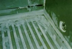 |
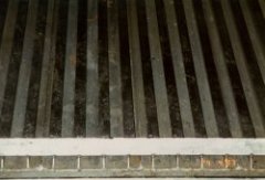
| Figure 90: Gratings in the floor of a refrigerated container, which ensure uniform distribution of the refrigerated air; Photo: U. Schieder |
Figure 91: A blocked defrost drain caused the water to flow out through the ventilation openings, where it froze. This blocked the floor gratings, so preventing sufficient air circulation. Photo: Nielsen [24] |
To ensure adequate circulation of the cold air, the floor is provided with gratings (see Fig. 90). Fig. 91 shows an incident of loss. In addition, the side walls of the container are "corrugated", which ensures satisfactory air flow there too. Fig. 92 shows several corrugations. When packing the container, suitable free space of approx. 15-20 cm must remain above the cargo in order to permit air flow here as well (see Fig. 92).
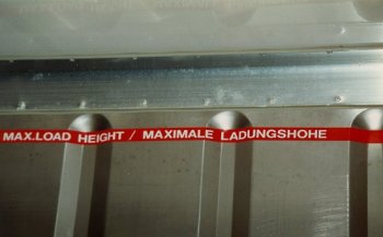 |
Figure 92: The red line in the container indicates the maximum cargo height. The free space above the red line ensures that the return air, which has been "warmed up" by the cargo stack, can flow back to the refrigeration unit. The corrugations in the outer insulation ensure that the cold air flows around the outside of the cargo block of the fully, flush-loaded container.
Photo: U. Schieder |
A mark indicates the maximum admissible cargo height. In usual container types, fresh air exchange is currently still adjusted manually; a microprocessor-controlled method has, however, been developed which makes it possible to carry out ventilation in accordance with a predetermined program. Using this method, it is possible, for example, not to begin ventilation until 72 hours have elapsed, in order to remove any heat which has been absorbed during packing. Ventilation may then be provided at specific time intervals in order to minimize any associated increase in temperature.
Use of additional intelligent sensors makes it possible to measure the carbon dioxide and/or oxygen content of the cooling air and adapt ventilation to the specific requirements for the particular product. Since ethylene production is proportional to carbon dioxide production, this ripening gas can also be successfully monitored in this way.
The doors constitute a weak point in both integral units and porthole containers. Wear to rubber door gaskets or improper handling may result in the doors no longer closing correctly, so that they are no longer sealed against rainwater and the like.

|
Figure 93: This container roof has suffered considerable damage during handling with a spreader. Photo: Nielsen [24] |
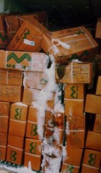
During transport of chilled and frozen goods, water ingress may lead to cargo spoilage or to ice formation in the door area (see Figs. 93-95).
 |
 |
| Figure 94: Damage to the container roof has resulted in warping of the doors. As a result, rainwater was able to get inside and formed a layer of ice in the door area. Photo: Nielsen [24] |
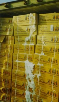
Figure 95: Rainwater has got inside in the door area in this case too, but the cause was a leaky rubber door gasket. Photo: Nielsen [24] |
In addition, refrigeration capacity has to be increased to compensate for losses due to cold air leakage. The temperature of the cold air which is blown in is recorded, for example, by means of a Partlow recorder or data logger (see TIS).