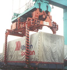
Problem-free dispatch has been assisted by the standardization of transport units, such as containers, while the standardization of certain components and some dimensions permits the use of standard handling equipment and means of transport.
We will describe fundamental components and designs first of all with reference to standard box containers. More detailed information is given under the heading "Container types".
 |
Basic container frame |
The load-carrying element of all box containers is a steel framework, consisting of four corner posts and two bottom side rails, two top side rails, two bottom cross members, a front top end rail and a door header.
 |
 |
|
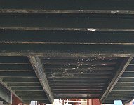
| Bottom cross members serve as supports for the container floor. | ||
Additional bottom cross members are fitted between the bottom side rails, to serve as supports for the floor covering.
 |
 |
|
| Side walls | End walls |
 |
Roof panel |
The side and end walls and the roof are the components of a standard box container which are capable of bearing the least load. To a certain degree, this naturally also depends on the construction materials used for them.
The following three Figures illustrate the essential components of standard box containers. Not included by name are, for example, the door bar handles, the locking components required for sealing, etc. Where necessary, descriptions of and comments about these components are provided at other points in the Handbook.
 |
|
| Essential components of a container |
 |
 |
|
| Part names in the area of the container floor | ||
A comparison of German and English part names is given below:
| German name | English name |
| Eckbeschlag | corner fitting; corner casting |
| Ecksäule | corner post |
| (unterer) Seitenlängsträger | bottom side rail |
| (oberer) Seitenlängsträger / Dachlängsträger | top side rail |
| unterer Querträger front also known as: Stirnschwelle rear also known as: Türschwelle / Türuntergurt |
bottom end rail; door sill |
| oberer Querträger / Dachquerträger front also known as: Stirnträger rear also known as: Türträger / Türobergurt |
front top end rail door header |
| Boden | floor |
| Stirnwand | front end wall |
| Bodenquerträger | bottom cross member |
| Dach | roof panel |
| Dachspriegel (e.g. in open-top containers) | roof bows |
| Seitenwände | side panel; side wall |
| Gabelstaplertasche | forklift pocket |
| Türverschlußstange | door locking bar |
| Scharnier | hinge |
| Nocke | cam |
| Nockenhalterung | cam keeper |
| Türdichtung | door gasket |
In the early days of container shipping, the majority of containers were constructed according to ASA standards, but now the containers used for maritime transport are almost without exception ISO containers.
 |
 |
 |
|
| ISO Corner Casting | ASA Corner Casting | ||
They differ both in dimension and in the shape of the corner fittings or "corner castings". Most ASA containers, i.e. containers like those used by Sealand constructed according to "American Standards Association" standards, have since been adapted to match ISO dimensions. To simplify handling, special universal spreaders were used, which could handle both types without difficulty.
 |
ISO corner castings - horizontal and vertical mirror images |
ISO standard 1161 specifies different shapes for top and bottom and mirror images for right and left.
The eight corner castings of a container or a corresponding CTU have to be particularly strong, since they work with the corner posts and the other basic components of the container frame to absorb the forces which lock units or lashings exert on containers when they are stacked on top of one another, during handling and during transport.
 |
 |
|
| Securing on board | ||
| Cargo handling |
 |
Securing on a chassis |
 |
||
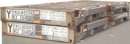
| DIN/ISO standards specify certain minimum requirements for the loading capacity and stackability of containers; while higher levels of performance may be provided for individual properties, lower levels may not. It must be possible to stack six ISO containers packed to the maximum weight vertically on top of one another. Maximum offset is set as follows: widthwise - 24.4 mm (1"), lengthwise - 38 mm (1�"). |
 |
The actual values of modern containers are generally higher. Many are designed to be stacked eight or nine high. The maximum stacking load must be marked on the CSC plate. (More details are given in the relevant section of the Handbook). |
According to safety regulations, stacked containers must where necessary be secured against toppling and shifting.
On larger container ships, the containers are stowed nine to twelve high in the hold. In such cases, the containers loaded must either be only partly full or designed to have greater stackability. The latter is generally the case with modern containers, but it is possible to use fold-out flaps in the cell guides, which subdivide the stacks.
 |
Indicating stacking heights on a container |
| Inland containers are only designed to be stacked three high when fully loaded. |  |
Irrespective of the material used to build a box container, it is essential for it to be spray-tight.
In standard box containers, the load-carrying parts are made of steel profiles, i.e. at least the entire frame including the bottom cross members and possibly also the elements serving as reinforcements, such as bottom side rails in the area of the gooseneck tunnel etc. Three main types of material are used for the walls and roof:
- steel sheet, corrugated
- aluminum sheet in conjunction with stiffening profiles
- plywood with glass fiber-reinforced plastic coating (plywood + GRP)
- steel container
- aluminum container
- plywood container
 |
 |
 |
 |
|
| Variously corrugated steel sheet | ||||
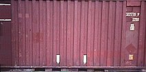
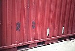
In steel sheet containers, a wide range of differently profiled corrugated steel sheet may be used for the outer walls. It is protected against corrosion by painting or similar processes.
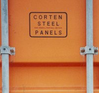 |
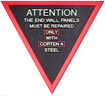 |
|
| Indication of container wall material | Repair instructions on a steel container |
The cost advantages of this type of container have led to its current dominance. Of all the containers currently in use, a rough estimate would suggest that 85% are made of steel sheet.
 |
 |
 |
|
| Aluminum container skin | |||
Aluminum containers are built either with a pure aluminum skin or with a plywood inner lining; they may also either be riveted or with a smooth or lightly riveted finish.
In plywood containers, the outer walls are made of plywood coated with glass fiber-reinforced plastic (GRP). Plywood is a popular material for "coffee containers".
 |
Container doors are often also made of plymetal, which consists of a plywood core with sheet metal adhered to it on both sides. |
 |
 |
|
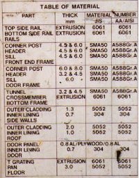
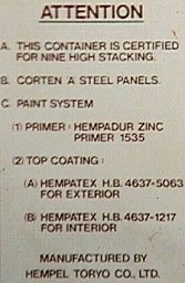
| Materials information on containers | ||
It is clear from these examples that containers are not generally made from a single material but various material combinations, here including steel, aluminum and plywood. The information even covers the type of preservatives used.
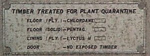 |
Wood treatment information |
Special impregnation against insect or other pests is required for certain regions of service. Most container floors or wooden parts undergo preventive treatment.
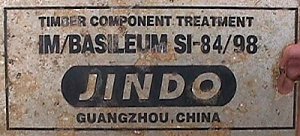 |
Wood treatment information | |
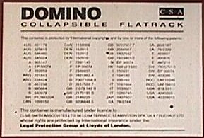
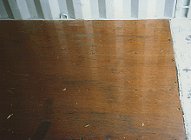
| Materials used for a flatrack |
 |
 |
 |
|
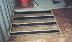
| Plywood floor | Repair to floor |
Box containers are predominantly provided with coverings of plywood or textured coated board mostly 25 mm thick, more rarely 30 mm thick. Although wood is relatively expensive, it has substantial advantages over other materials: it is strong and resilient, does not dent, may be easily replaced during repairs and, when appropriately finished, has an adequate coefficient of friction. The latter does not apply to the virtually new container in the left-hand Figure, which has a mirror-bright finish.
| Cross-section through a seven-ply plywood board |
 |
 |
 |
|
| Planking | Steel floor | ||
Planking is preferred for flatracks and other similar platform containers. 20' platforms or half-height open-top containers often have a floor of steel, e.g. of "tear drop" or otherwise textured sheet.
The floors of ISO containers have to be capable of bearing the evenly distributed payload, the emphasis being on "evenly distributed".
The following test criteria apply where ground conveyors have access to container floors.
| Axle load | 12,040 | lbs / 5,460 kg |
| Wheel load | 2,730 | kg |
| Contact surface per wheel | 142 | cm² |
| Wheel width | 180 | mm |
| Wheel gage | 760 | mm |
The wheel contact area of 142 cm² corresponds approximately to the size of a postcard. Forklift trucks with a load-carrying capacity of 2 metric tons have axle loads of just under 5 metric tons when loaded. Most 2.5 metric ton forklifts are within the admissible range. However, some electrically operated 2.5 metric ton forklift trucks reach front axle loads of over 6,000 kg when loaded. It is of course possible for even heavier forklift trucks to drive into containers, provided they are not fully loaded and the equipment and cargo dimensions allow it. It is essential to note that add-ons reduce the load-carrying capacity of forklifts, but increase the front axle load. Goods may only be stacked in box containers using equipment with a suitable telescopic mast. Using equipment with twin tires may reduce the wheel loads, but it doesn't completely resolve the issue of axle load. It shouldn't therefore be regarded as a license to use heavier equipment.
The strength of ISO containers is laid down in the relevant DIN standards and/or the International Convention for Safe Containers:
ISO containers must be capable of absorbing the horizontal forces arising during regular service at the level of the end frames.
 |
Longitudinal loading capacity in the floor area |
Containers must withstand loads in the lengthwise direction which correspond to external acceleration of 2 g acting horizontally on the floor fastening elements. This takes into account loads which are transmitted via twist locks and other vehicle locking elements to containers. Special railroad container cars with hydraulic shock absorption limit forces to 2 g; examples of these cars are Lgjs, Sgjs and Sgjkmmns cars and other cars with a j in their name, the j indicating high-performance (long-stroke) shock absorbers or buffers.
 |
According to the CSC, end walls must be so constructed that forces of 0.4 times the uniformly applied payload may be absorbed, i.e. 40% of the container payload or 0.4 g. Higher or lower values should be marked on the containers. | |
| End wall loading capacity |
| The loading capacity of the side walls must correspond to 0.6 times the uniformly applied payload, i.e. 60% of the payload or 0.6 g. Higher or lower values should again be marked on the containers. More details are given in Section 3.1.2 CSC & structural and testing regulations". |  |
|
| Side wall loading capacity |
Since the values for end and side walls are valid only for large-area loads, any point loading of the walls should be avoided. Because the weight-carrying capacity of many general purpose containers is not fully utilized, loading is kept below the maximum values in the case of compact and even packing. However, if the rate of utilization is high and/or uneven, countermeasures must be taken.
 |
In the case of container roof panels, an evenly distributed 200 kg load may be applied to a surface area of 600 x 300 mm, so meaning that two people may stand next to one another on the container roof. Under no circumstances may container roof panels be covered with cargo. |
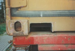
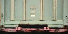
Some containers are fitted with forklift pockets for handling with ground conveyors. Appropriate regulations relating to the required dimensions may be found in appendix C of ISO 1496/1. The pockets are cavities formed crosswise in the floor structure and allow insertion of the forks from the side; the forks must be pushed fully into the pockets. Forks which are too short must under no circumstances be used for lifting, since they may cause damage to the floor.
 |
Unmarked forklift pockets on a box container. |
The forklift pockets generally only allow handling of empty containers. Packed containers must not be picked up in this way unless specifically permitted. This is not the case here; hence, the container may only be picked up with forks when empty.
 |
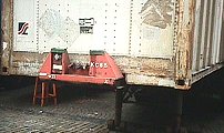
Forklift pockets on a flatrack marked EMPTY |
| Forklift pockets on a flatrack not marked EMPTY |
 |
 |
|
| Both containers may only be picked up when empty. | ||
For the most part, no marking is provided or no explicit instruction is given to pick up only empty containers, missing. To rule out errors, marking should be made a requirement.
 |
 |
||
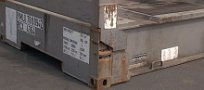
| Marking variant: the arrows bear the mark "Tare". | |||
The containers shown here merely bear the marking "Tare" at the inner forklift pockets. The outer pairs of pockets lack markings or symbols. It is obvious here that the arrangement of these pockets also allows handling of the full container by forklift truck, but one can never be sure. This example shows that there is a need for marking to be mandatory.
| Forklift pockets on a "tilt" container |
With this container, it is even less certain how the forklift pockets are to be used. Standardized regulations and compliance therewith in practice could help in the avoidance of many losses resulting from the incorrect use of these components.
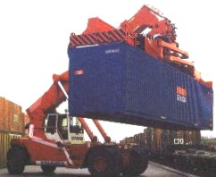
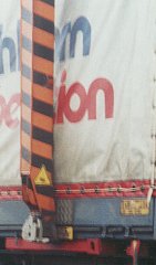
| Straddle carrier recess |
Some containers have a recess along the longitudinal sides which allows the containers to be picked up using straddle carrier load suspension devices for transport within cargo handling facilities. Straddle carriers are specially built (low) van carriers with which loads may be lifted but not stacked.
 |
 |
|
| Handling a swap-body with grappler in grappler pockets |
||
 |
 |
|
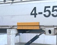
| Grappler pocket in a semitrailer | Grappler pocket in a swap-body |
Grappler pockets are slots or recesses in the bottom side rails of containers or other CTUs, especially inland containers and swap-bodies. Grapplers slot into them during cargo handling. Such grapplers may also be used with gantry cranes, if no spreaders are used. Grappler pockets also allow direct pick-up of the containers with the tongs of a van carrier.
 |
 |
 |
|
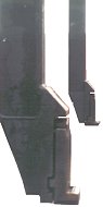
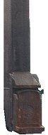
| Detailed images of grapplers | |||
 |
 |
|
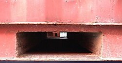
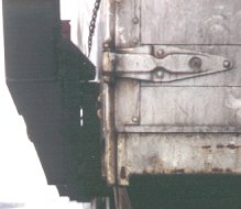
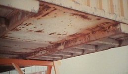
| Gooseneck tunnel | ||
Many containers have recesses in the bottom of the front end This centrally located recess is known as a gooseneck tunnel. A large number of CTUs, especially flatracks have them at both ends. The tunnel does not have any effect on loading space, the inside of the container floor or the flatrack loading area being flat. This recess serves in centering the container on a gooseneck chassis.
 |
 |
|
| Container with gooseneck tunnel on a normal container chassis |
Container with gooseneck tunnel on a gooseneck chassis |
Containers with goosenecks can be carried on both normal chassis and gooseneck chassis. Containers without goosenecks can only be carried on normal chassis. Depending on the construction of the chassis, a lower road vehicle overall height may be achieved with gooseneck chassis. In this way, many articulated trucks can see their height reduced by approx. 150 mm.
 |
 |
|
| 40' flatrack with gooseneck tunnel |
20' flatracks without gooseneck tunnel |
In accordance with the standards, gooseneck tunnels are only provided for 40' containers.