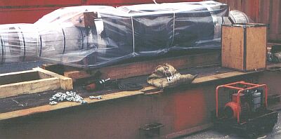
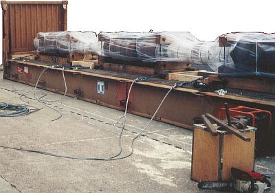
Example 1: Three plant parts on a 40' flatrack
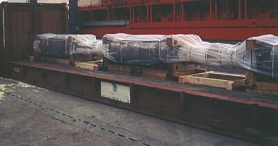 |
A considerable amount of material was wasted securing the cargo lengthwise with wooden bracing. Although it looks expertly done, there are a number of deficiencies.
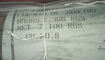 |
The gross weight of each of the three parts is stated as 7,366 kg. Thus, the total weight loaded on the flatrack is 22,098 kilograms, corresponding to normal forces of 7,226 daN per item or 21,678 daN for the whole cargo.
 |
|
| Basic diagram of the cargo |
Taking the maximum possible lengthwise acceleration of shipment of 1 g as the basis for calculation and leaving possible frictional forces out of the consideration, the following securing forces must be produced in the lengthwise direction:
- at the end walls at (a) 3 x 7,226 daN = 21,678 daN;
- between the items of cargo (b) 2 x 7,226 daN = 14,452 daN.
If the load bears on bracing lumber against the face grain, i.e. if the lumber is used perpendicularly to the grain, 30 daN per square centimeter of lumber cross-section may be applied. The lumber cross-sectional area would accordingly have to be 723 cm² at points (a), and 482 cm² at points (b).
 |
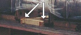
| Above and right: incorrectly applied bracing means material wastage |
 |
 |
||
| Basic diagram of the chosen bracing method | ||
With the chosen method of bracing, wooden lengthwise members and crosspieces have been fitted on the flatrack floor between the plant parts' "wooden sled members" without taking account of their height.
Using 14 x 14 cm lumber on the flatrack floor and the same size lumber for the higher "wooden sled members" of the plant parts results in a contact surface of only approx. 2 x 14 cm x 7 cm = 196 cm², so meaning that the cargo is inadequately secured. It is also unfavorable that crosspieces have been used which are stressed perpendicularly to the grain, despite the fact that the sled lumber is capable of bearing loads against the end grain. Appropriate securing could have been achieved with a quarter of the volume of lumber used.
 |
||
| Cost-effective bracing | ||
Since, when the lumber is exposed to stress against the end grain, an effective lumber cross-section of only 145 cm² is required to absorb 14,452 daN of longitudinal forces, two squared lumber members 8 cm x 10 cm nailed under a board and suspended from above and nailed to the wooden sled members would have sufficed.
 |
||
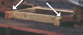
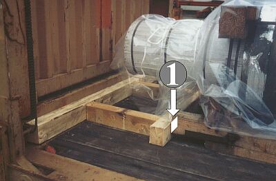
| Incorrect use of bracing lumber at the end of the flatrack | ||
Some of the possible lumber loading capacity has also been wasted at the end, because the bracing has not be applied at the level of the wooden sled members, so making the effective lumber cross-sectional area smaller than was possible.
 |
||
| Possible bracing, provided that the front end wall has sufficient loading capacity | ||
In order to be able to introduce forces of 21,678 daN into the front end wall, the wall must be capable of withstanding point loads at the appropriate places. If it is, the method illustrated may be used for cost-effective securing, since a lumber cross-sectional area of only 217 cm² is required and consequently of only 109 cm² per bracing member. Sufficient securing is achieved with only two 10 cm x 12 cm wooden members.
 |
||
| Bracing with pressure-distributing measures | ||
If the front end wall is not able to withstand point loads, crosspieces must be fitted. Since the bracing members bear on the face grain of the crosspieces for pressure distribution, strength values of only 30 daN/ cm² must be assumed. Consequently, at 21,678 daN, a surface area of 723 cm² is required, or a cross-sectional area per member of 362 cm² if two members are used. Lumber 18 cm x 20 cm or with a similar cross-section would be necessary. In the packing example selected, this is impossible, since the sled lumber has a smaller cross-sectional area due its smaller size. As no changes can be made to the sled under the plant parts, there are three possible options:
 |
||
| Changing the strength of the lumber by using hardwood | ||
The strength of the crosspieces may be increased by using hardwood beams. In the example described, it is sufficient for just the upper beam to be replaced by beech or oak.
 |
||
| Enlargement of the area by steel angle plates | ||
Load transfer from the wooden bracing members loaded against the end grain and with a strength of 100 daN/ cm² to the 30 daN/ cm² crosspieces loaded against the face grain may be improved by fitting steel angle plates to increase the area for load transfer.
The third option is to transmit only a proportion of the longitudinal forces via wooden bracing and to absorb the remaining forces by means of lashing. This option has always to be considered when the front end wall of the container is insufficiently strong to absorb the necessary securing forces.
 |
||
| An "over-the-top" approach to securing | ||
Here, much energy is being expended to secure the plant parts appropriately. Chain saws, steel wire ropes, wire clips, turnbuckles etc. have all been used, despite being unnecessary.
 |
||
| Preparation for cargo securing | ||
The following pictures show that, despite all this effort, the objective has not been achieved:
 |
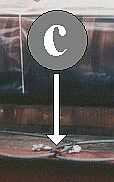 |
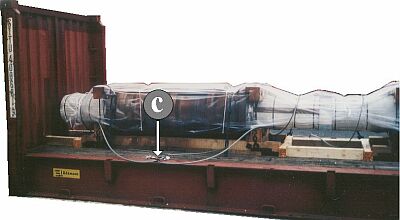
Top Above and selective enlargement to the left: Nonuniformity of lashings |
Two steel ropes 16 mm in diameter, with which a maximum securing load per rope of 10,240 daN can be achieved in expert hands, are attached to lashing point (c), which can take a maximum securing load of approx. 3,000 daN. The intention was apparently to assist the obviously too small wooden bracing members by attaching the wires. They are intended to be effective in 3 directions: lengthwise, crosswise and vertically. The greatest attention is paid to the lengthwise component.
If sufficient wooden bracing is provided in the lengthwise direction, as already explained, sensible crosswise and vertical securing is lacking, a problem which can be readily solved with laterally acting loop lashings around the plant components. For this to be feasible, however, the nature of the cargo does have to allow the use of loop lashings.
 |
||
| Crosswise and vertical securing by loop lashings, applied to separate lashing points. | ||
In the case of a normal force of 7,226 daN per item, in the least favorable case transverse acceleration of 0.8 g and forces in the region of 5,780 daN have to be expected. The cargo dimensions result in average vertical lashing angles α of approx. 30°. The vertical component of a lashing thus amounts to approx. 50% and the horizontal component amounts to approx. 85% of the maximum securing load.
If single-use webbing belts with a maximum securing load of 2,000 daN are used, horizontal forces of 2 x 2 x 2,000 daN x 0.85 = 6,800 daN can consequently be achieved with the two loop lashings on each side. The vertical component of the four loop lashings then amounts to 8,000 daN, calculated from 4 x loop lashings each having two working parts x 0.5 for the lashing angle α x 2,000 daN maximum securing load.
In the example, the ends of the loop lashings are applied separately to different lashing points. It is assumed that the lashing points have a maximum securing load of at least 2,000 daN. The horizontal lashing angle β of approx. 12° should be disregarded, since a value of 0.995 is obtained for the cosine of 6° in accordance with the formula cos β/2. This reduction of 5 thousandths understandably does not need to be taken into account.
 |
||
| Crosswise and vertical securing by loop lashings, applied to a single lashing point |
||
If the maximum securing loads of the available lashing points are at least twice that of the lashing materials used, the two ends of each loop lashing may be attached to one lashing point or guided around it.
Materials other than the above-mentioned single-use webbing belts can also be used for securing. However, any equipment used must be as economic as possible to use and not cause any damage to the shipping packages.
If the nature or sensitivity of a cargo forbids fastening to or around the cargo itself, securing may achieved by including the cradles, if they are as sufficiently strong as the components described above. This requires the cradles to be specially constructed, with routed grooves, recesses in the lumber or the like, but, if planned in good time, such measures do not involve excessive effort.
 |
||
| Crosswise and vertical securing by loop lashings passed around the cradles. | ||
Since the above-described securing measures may damage the film applied to the packages, it is essential for cargo items which need to be kept dry to be provided subsequently with sufficiently tear-resistant protection against the weather, which must be applied in such a way that it cannot be damaged by wind forces during a voyage.
If the ends of the plant parts are capable of bearing a load, they may be secured with loop lashings. The advantage of this is that the smaller diameters result in more favorable transverse components:
 |
||
| Securing at the ends of plant parts - side view | ||
 |
||
| Securing at the ends of plant parts - plan view | ||
The path taken by the loop lashings is more clearly visible in the following Figures:
 |
||
| Securing at the ends of plant parts - detailed side view | ||
 |
||
| Securing at the ends of plant parts - detailed plan view | ||