winding axis horizontal and crosswise
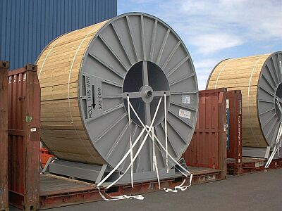
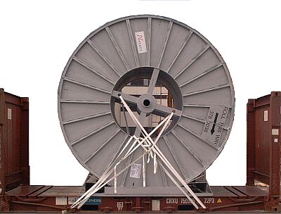
Particularly heavy cable reels on 20' flatracks
 |
Some reel labeling details |
For a voyage to Indonesia, these reels need particularly careful securing, since the probability that the ship will meet with bad weather increases with the length of the voyage.
 |
|
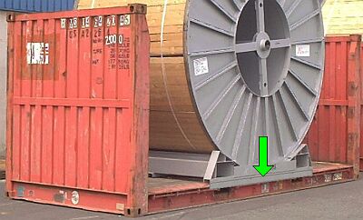
| Heavy, bulky cable reels on 20' flatracks |
 |
|
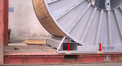
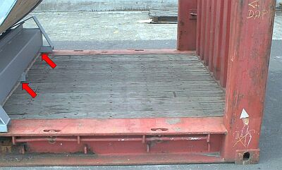
| Poorly constructed floor assembly made from U-profiles |
It was foolish of the manufacturer to choose a floor structure of three U-profiles extending perpendicularly to the reel axis. Its six steel strips provide so little surface area that laying friction-enhancing underlays is pointless.
  |
|
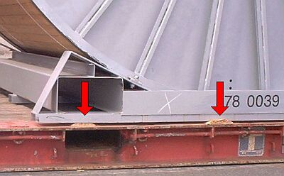
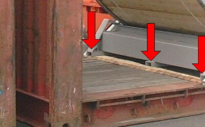
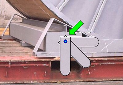
| Squashing of the boards laid underneath due to excessively small bearing areas (selective enlargement below) |
 |
|
| Floor structure and underlays cause extremely high pressures. |
The boards laid underneath are squashed by the extremely high pressures. If four approx. 200 mm wide boards are laid underneath and the steel thickness of the 3 U-profiles is 8 mm, the bearing area is 24 x 200 mm x 8 mm = 38,400 mm² or 0.0384 m². With a cable reel gross weight of 24,481 kg or a normal force of 240,159 N, the pressures are 6,254,141 pascals, i.e. approx. 6.3 MPa. This would previously have been written as 637 metric tons/m².
 |
|
| Per transverse board, the load is distributed over six tiny strips. |
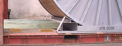
It would have been better to omit the boards and to have laid the cable reel directly on the flatrack. However, friction is reduced markedly thereby, since at the outside steel is resting on steel. The use of strips of friction-enhancing mats is out of the question, since they would be cut and chafed in transit by the heavy load.
 |
|
| Floor structure with integral friction-enhancing material |
The manufacturer of the cable reels or floor assemblies for them may assist in subsequent cargo securing by incorporating squared lumber and friction-enhancing material into the U-profiles.
 |
|
| Preparation of inadequate "securing means" from single-use webbing belts |
The initial securing stages illustrated here are wholly inadequate. On the one hand, webbing belts must be applied over a large area, which is impossible here; on the other hand, the chosen securing methods are not capable of holding the approx. 25 metric ton mass on the flatrack over an extended period.
 |
|
| Inadequate "securing" with single-use webbing belts |
Even if it is assumed, incorrectly, that 3,000 daN of lashing force could be produced with a textile strap, the horizontal lengthwise securing force would amount to 1,500 daN in the longitudinal direction because of the lashing angle. The vertical component amounts to 2,100 daN. The method of application means that the cable reels are virtually unsecured in the transverse direction.
 |
|
| Lateral securing using steel edge provided at the design stage |
The cable reel could be held absolutely securely on the flatrack if the manufacturer had given some thought to cargo securing from the outset. A steel edge which is welded on or can be bolted on ensures 100% secure lateral securing.
 |
|
| Lateral securing option using steel lugs |
Steel lugs provided at the design stage, which may even be adjustable in the transverse direction, would be another possible way of ensuring transverse securing. A large number of other options is feasible - it is not unreasonable to expect the manufacturer's engineers and technicians to display a little imagination.
 |
||
| Lengthwise securing using squared lumber | ||
Appropriate lengthwise cargo securing can be readily achieved by using squared lumber bracing.
 |
||
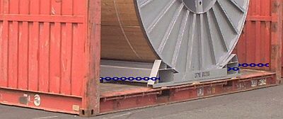
| Lengthwise and transverse securing using chains | ||
 |
||
| Lengthwise and transverse securing using chains - plan view | ||
The use of chains allows securing to be achieved in both the transverse and lengthwise directions. Because of the package dimensions and the lashing points provided, the transverse components turn out to be greater than the lengthwise components. To achieve adequate securing, several chains should be used or the longitudinal components should be supplemented by additional squared lumber bracing.
 |
||
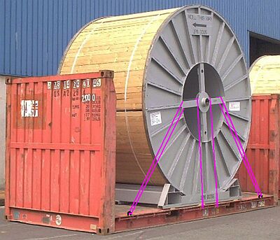
| Vertical securing and securing against tipping using vertical and oblique lashings | ||
Provided that the cable reel is secured adequately in the floor area against lengthwise and sideways shifting, vertically and obliquely applied lashing are sufficient to secure the cable reel against tipping and other vertical forces.
Cable reels on 40' flatracks
 |
||
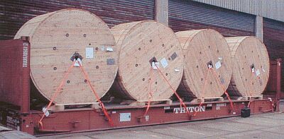
| Inadequately secured cable reels on a 40' flatrack | ||
The two outer reels are not stowed with a tight fit against the end walls of the flatrack. Lengthwise securing is achieved by the lashing belts passed through the eye. The effective horizontal component amounts to approx. 40% of the maximum securing load. In the case of lashing belts of 2,000 daN maximum securing load, each cable reel would be secured with 2 x 2,000 daN x 0.4 = 1,600 daN in each longitudinal direction. However, this theoretical value is not achieved, since the webbing belts are not used properly. The useful maximum securing loads cannot therefore be determined.
 |
||
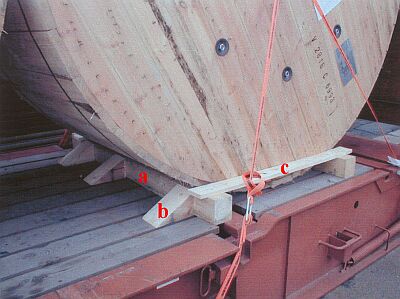
| Detail of the floor area of a cable reel | ||
The squared lumber (a) laid crosswise can only contribute to a small degree to lengthwise securing due to the incorrectly cut wedges (b. The wooden members (a) are only held together minimally by the nailed-on board (c). In addition, board (c) constitutes the only transverse securing, since the webbing belts only hold the cable reel by means of the vertical pretension component together with friction. The resultant values are minimal.
To sum up: cable reels cannot possibly be sent on a voyage like this. With the exception of ships with flaps, in which stowage is also possible in the bottom of the ship, flatracks will most probably be stowed in the top tier below deck or on deck.
In general, the following procedure can be followed for such cargoes:
 |
| Above and selective enlargement to the right: Compact stowage of relatively light cable reels: gaps filled at the end |
 |
|
The reels are loaded onto the flatrack. To prevent accidents, each reel should provisionally be prevented from rolling by wedges, beams or the like. If gaps are left at the front end wall, they should be filled with squared lumber, planks or boards (1). The bracing should be directed inwards from the external edge of the reels, so that the high strength of the outer panels of the reels is utilized.
 |
 |
Above and selective enlargement to the left: Compact stowage of relatively light cable reels: gaps in the middle |
Loading from the ends to the middle is easier. To brace the gap remaining in the middle, only half the lumber cross-section is required, because only half the load is applied to the lumber (1). Care is required if, in the case of reels of the size shown in the end area, container handling could be obstructed.
In the case of a mass per cable reel of only 3,000 kg, i.e. 12,000 kg altogether, the end walls of the flatrack can still withstand forces which would result from acceleration of 1 g.
 |
|
 |
Above and selective enlargement to the left: Packing variant - larger gaps in the middle |
If larger gaps (1) remain, it is always better to leave these in the middle and brace them.
So that the wooden members are held secure, they should be connected together transversely by wooden boards. Attachment to the boarding of the cable reels requires the greatest of care, in order not to damage the cables.
 |
|
| Impractical: Leaving several gaps and bracing them |
Since the end walls of the flatrack can be loaded with 0.4 times the payload, all that is needed to achieve adequate securing of a cargo of a total mass of up to 40% of the payload is compact stowage or filling of the gaps.
 |
|
| Relieving the load on the end walls by lashings |
If the mass of the cable reels to be stowed exceeds this value, the load on the end walls of the flatrack must be relieved by inwardly tensioned lashings (2). Loop lashings passed through the eye and pulled towards the middle of the flatrack are best suited to this task. Number and type and thickness of material depend on the maximum securing loads of the lashing points on the flatrack and the values of the acceleration to be taken as basis for the particular transport. When calculating corresponding numerical values, coefficients of sliding friction must not be taken into consideration, since the cable reels can roll when stowed in the ways shown so far.
 |
|
| Diagram showing the principle of individual lengthwise cable reel securing |
If the total mass of the cable reels reaches the payload of a flatrack, load distribution could look like this in the case of uniform stowage. However, the disadvantage is that only some of the end wall strength is utilized. If each reel exhibits 25% of the payload mass, while the end walls can be loaded with 40% of the payload, 15% of the strength is wasted. If, as is shown here deliberately, the lashing angles differ, the maximum securing loads of the lashings would likewise have to be different.
 |
|
| Variant of individual lengthwise securing |
If the mass of the cable reels reaches the payload of the flatrack, and longitudinal accelerations of 1 g are assumed, the stowage method illustrated is particularly favorable from the point of view of cargo securing. Since 50% of the payload has been packed against each end wall, but the end wall themselves can only bear 40%, the lashings (1) have only to take up forces produced by 10% of the cargo mass and the 1 g acceleration. However, the lashings (2) and (3) have to be so strong that their effective force components correspond to the forces resulting if the mass of a cable reel is multiplied by the assumed acceleration.
 |
|
| Lateral securing using loop lashings through the eye |
Provided that stanchions are not provided for bracing purposes, lateral securing of cable reels may be ensured by loop lashings through the eye.
 |
|
| Loop lashings through the eye of a cable reel |
The red and purple loop lashings secure each cable reel against movement to one side while the green and blue secure against movement to the other side. To calculate the necessary maximum securing loads, the corresponding coefficients of sliding friction can here be taken into consideration. Using friction-enhancing materials under the reels can have a considerable effect on the material thicknesses required.
It should be noted that loop lashings through the eye produce almost no lengthwise securing forces.
N.B. In the case of cable reels which are stowed with their axis lying horizontally, it is essential to check that the container's admissible line loads are not exceeded and that no excessive point loads arise.