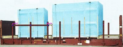
Two cases of approximately equal weight on a 40' flatrack
 |
|
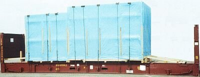
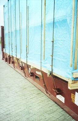
| Inadequately secured cases on a 40' flatrack |
It is immediately obvious that the lengthwise securing on the right-hand side of the flatrack is inadequate, since nailed-on wooden members have been used. To assess the rest of the securing arrangement, a closer look is required. Positive features are that the weather protection is better than that provided for the previous cases and that the steel wire tie-down lashings are passed over elastic edge protectors.
 |
|
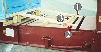
| Inadequate securing with wooden fixings |
When building the technically skillful construction, no consideration was given to the fact that only the shear action of the nails hammered into wooden members (1), (2) and (3) is relevant to the strength of the overall structure. Depending on the thickness of the flatrack planking and the selected wire nail diameters, together with their depth of penetration into the wooden members and the floor, cohesive resistance of approx. 100 - 400 daN per nail may be anticipated.
 |
|
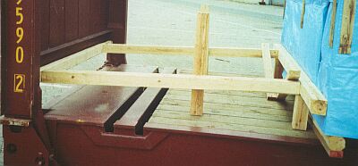
| Wooden bracing on the left-hand side of the flatrack |
The bracing on the left-hand side of the cases is passable. However, it must be ensured that the bracing cannot loosen, for which purpose the squared lumber must be carefully tacked down. The following approach is somewhat more elegant.
| Variant of bracing on left-hand side |  |
Depending on the desired height, a number of wooden members laid cross- and lengthwise are used as a base. Two boards (1) cut to the right dimensions are laid lengthwise thereon. The wooden members (2) and (3) serving to distribute pressure are placed crosswise on the ends thereof. Finally, the wooden members (4) need to be cut precisely to size and fitted in place.
 |
Inadequate securing against crosswise and tipping movement using tie-down lashings |
The front case is secured with five tie-down lashings made from steel wire ropes 16 mm in diameter, while the rear case is secured with three. The maximum securing load of the wire ropes may be calculated by rule of thumb in decanewtons on the basis of d x d x 40, i.e. 16 x 16 x 40 = 10,240 daN. If three wire clips are used, a maximum of 7,680 daN is achieved per single run of lashing. The lashing points used have on average a maximum securing load of approx. 3,000 daN. The wires are pretensioned with turnbuckles. If the maximum allowable pretension is 50% of the admissible lashing force on each side, a total of 2 x 1,500 daN = 3,000 daN pretension could be applied per lashing. Assuming a coefficient of sliding friction of μ = 0.2, securing forces of 600 daN should be anticipated per tie-down lashing. The reduction in forces due to the lashing angle of approx. 70° was disregarded. The large case has accordingly been secured by the tie-down lashings in all horizontal directions with 5 x 600 daN = 3,000 daN, while the small one has been secured with 3 x 600 daN = 1,800 daN. By using friction-enhancing material with a possible coefficient of sliding friction of μ = 0.4 under the stowed cargo, the values could have been doubled.
The best possible securing arrangement for the two cases would be:
- use of case restraint shoes or specially shaped stanchions for lateral securing
- use of two tie-down lashings in each case to secure against tipping
- application of wooden bracing for lengthwise securing
  |
|
| Securing variant for unilaterally overhanging cargo, using the stanchions provided (selective enlargement below) |
On the side of the flatrack remote from view, the third stanchion from the left is inserted. On the visible side, all the stanchions are inserted. A squared lumber member is fastened vertically to the inside of each of the three front stanchions on the left-hand side. The height of these squared lumber members should correspond to half the case height. Two of the unused stanchions from the other side are laid lengthwise on these squared lumber members and attached to the stanchions.
| Inserted stanchions on the flatrack sides - plan view |
The two cases are loaded and secured as illustrated.
 |
 |
|
 |
|
| Overview of securing arrangements (center and bottom: enlargement of the first picture in two halves) |
|
Case (a) is supported by means of the horizontally attached stanchions (1) and (2), which are fastened to the inside edge of the stanchions (3), (4) and (5). Case (b) is supported against stanchions (6) and (7). Bracing is provided in gaps (c), (d) and (e) between the cases and the end walls of the flatrack and those between the cases in the form of squared lumber and planks. Likewise, the stanchion (5) is braced crosswise at (9) with the opposite stanchion. The bracing is shown in detail below:
 |
|
| Bracing of the gaps (c), (d) and (e) and the stanchion pair at (9) |
Bracing of the stanchions is intended to ensure that, when the cases are subsequently lashed at stanchion (5), the moments of resistance of two stanchions can be utilized due to the bracing (9), given that two lashings are attached to the stanchion (5).
 |
|
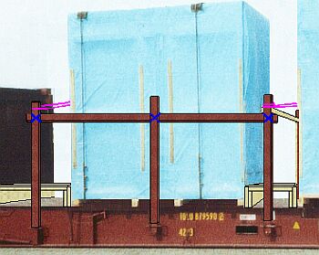
Mutual bracing by the pairs of stanchions Top: plan view - Bottom: end-on view |
The following Figure shows securing of the left-hand case in detail:
 |
|
Detail: securing of left-hand case |
Key to reference numerals/letters:
| a | = | left-hand case |
| c | = | gap between case and flatrack end wall |
| 1 and 2 | = | stanchions attached horizontally lengthwise |
| 3, 4 and 5 | = | stanchions |
| 9 | = | bracing between stanchion 5 and opposite stanchion |
| 10 | = | direct lashing to hold the case laterally on the "open side"; the lashing means is passed from stanchion 3 horizontally around the case to stanchion 5 |
| f | = | tie-down lashings |
The following Figure shows securing of the right-hand case in detail:
|
||
 |
Detail: securing of right-hand case (left: enlargement of the left-hand part of the top picture) |
|
Key to reference numerals/letters:
| b | = | right-hand case |
| d | = | gap between cases a and b |
| e | = | gap between case and flatrack end wall |
| 5, 6, 7 and 8 | = | stanchions |
| 9 | = | bracing between stanchion 5 and opposite stanchion |
| 11 | = | direct lashing to hold the case laterally on the "open side"; the lashing means is passed from stanchion 5 horizontally around the case to stanchion 8 |
| f | = | tie-down lashings |