Effective securing forces can be calculated from material strengths and lashing angles. The strength of lashing points is sometimes shown on flatracks.
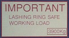 |
While the meaning of "safe working load" is clearly defined for load suspension devices in hoist operation and loading gear, it is not for lashing points on containers.
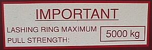 |
And what are packing personnel to make of "maximum pull strength"? The "Guidelines for the correct stowage and securing of cargoes for carriage in ocean-going ships" provide, in particular in Appendix 13, information about nominal breaking load (BL) and maximum securing load (MSL).
If no information is provided on CTUs with regard to the strength of lashing points, or if such information is unclear, the rules of thumb published in the above guidelines should be applied.
The breaking load of lashing rings or bars etc. may be calculated using the rule of thumb d² × 20, i.e. diameter x diameter x 20. The maximum securing load (MSL) should amount to at most 50% of the breaking load. The result of this rough calculation is a value in kN if the diameter unit used is centimeters and in daN if the diameter unit used is millimeters: In accordance with the above explanations, maximum securing load is accordingly half the nominal breaking load (BL), i.e. MSL = BL/2.

Determining the diameter of lashing points
If the diameter of a lashing point is measured as 2 cm or 20 mm, the nominal breaking load (BL) can be calculated as follows:
| BL = | d ×d ×20 = | 2 × 2 × 20 = | 80 [kN] |
| BL = | d ×d ×20 = | 20 × 20 × 20 = | 8,000 [daN] |
Since the MSL can amount to at most half the BL, the MSL is determined as follows:
| MSL = | BL/2 = | 80/2 | = 40 [kN] |
| MSL = | BL/2 = | 8,000/2 | = 4,000 [daN] |
The flatrack loaded with the slab has lashing points 20 mm in diameter. Using the two loop lashings, it is possible to achieve lashing forces (in relation to the lashing points) in each sideways direction of 4 × 40 kN = 160 kN or 4 × 4,000 daN = 16,000 daN. This is entirely sufficient because with a mass of 23,463 kg or a normal force of 230,172 N and assuming sideways acceleration of 0.8 g and a coefficient of sliding friction of μ = 0.4, securing forces of 92,065 N must be applied; these amount to 9,206.5 daN or 92.065 kN.
Obviously, in this case, the maximum securing load can be calculated without passing via the nominal breaking load. The maximum securing load of lashing points can be calculated from the rule of thumb d² × 10, as the MSL may at most be only half the BL. The calculation is then as follows:
| MSL = | d ×d × 10 = | 2 × 2 ×10 | = 40 [kN] |
| MSL = | d ×d × 10 = | 20 × 20 ×10 | = 4,000 [daN] |
This simplified calculation can be used whenever the ratio between BL and MSL is a round number, otherwise it is always better to calculate the BL first and then the MSL.