 |
 |
 |
|
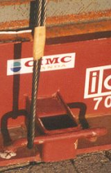
| Steel wire rope | Lashing point | Steel strap |
 |
 |
|
| Inspecting and measuring lashing equipment | ||
Note: Sections in italics have been reproduced from seminar material by kind courtesy of Captain Hermann Kaps, professor at the University of Applied Sciences in Bremen.
Fundamental terms
kilonewton (kN) is a unit of force useful for describing for instance the breaking strength or breaking load of load securing material. It has replaced the previously common metric ton which is the unit reserved for describing mass according to the SI standard. The conversion is easily learned: 1 kN ≡ 0.1 t or 100 kg.
Anyone who was used to calculating mass in kilograms can use the unit decanewton (daN) as a unit of force.
The following English terms are in common use in maritime transport across the world.
Securing element is an individual item of equipment on board ship which is used for load securing, e.g. a shackle, a deck ring, a turnbuckle, chain or wire rope.
Securing device is a suitable combination of elements which together form a means of load securing, e.g. lashing or bracing.
Securing Arrangement is a reasonable arrangement of load securing means with the aim of securing a cargo item or a cargo block.
Breaking Load (BL) is the nominal breaking load, generally specified by the manufacturer. However, it can also be estimated using rules of thumb.
Maximum Securing Load (MSL) in kN, is the greatest permissible force which can be applied to a load securing element or device.
Calculation Strength (CS) in kN, is an arithmetic force determined by reducing the MSL by the formula: CS = MSL / 1.5. CS values are only used to assess the efficiency of securing arrangements as per Annex 13 of the CSS code.
The relation between Breaking Load and Maximum Securing Load is shown in Annex 13 by the following table:
| Material | MSL |
| Shackles, rings, deck eyes, turnbuckles of mild steel |
50% of breaking strength |
| Fiber ropes | 33% of breaking strength |
| Web lashing | 70% of breaking strength |
| Wire rope (single use) | 80% of breaking strength |
| Wire rope (re-useable) | 30% of breaking strength |
| Steel band (single use) | 70% of breaking strength |
| Chains | 50% of breaking strength |
| lumber | 0.3 kN per cm² normal to the grain |
Table: Determining the MSL from the breaking load
Lashing elements and lashing materials There are no international standards on tie down lashings. It is to be expected, however, that manufacturers or dealers will provide information on or certification of the nominal breaking load on purchase. It is, however, generally unclear how this value was determined and under what conditions it is valid. No reference is made to any other properties, such as elasticity and fatigue strength.
The table below provides a list of the most important materials and elements with the usual characteristic values. An accepted rule of thumb is used for the breaking load.
If millimeters are chosen instead of centimeters for the dimensions, the breaking load values will be in decanewtons [daN] instead of kilonewtons.
| Material/element | Breaking load [kN] | Notes |
| Natural fiber ropes (manila, sisal, hemp) | 6 x d² | d = diameter of rope in cm. Natural fiber ropes are sensitive to decay, acids and alkalis. All fiber ropes are sensitive to chafing from sharp edges. Knots on synthetic fiber ropes can slip open. Heavers of sufficient thickness should be used to tighten them and these in turn should be secured to prevent them from unwinding. |
| Polypropylene | 12 x d² | |
| Polyester | 15 x d² | |
| Polyamide | 20 x d² | |
| Hercules (sisal) | 6 x d² | |
| Hercules (polypropylene) | 12 x d² |
| Material/element | Breaking load [kN] | Notes |
| Wire rope 6 x 9 + 1 FC Wire rope 6 x 19 + 1 FC Wire rope 6 x 37 + 1 FC |
50 x d² | d = diameter of rope in cm. Producing conventional wire rope lashings with turnbuckles and rope clips is technically demanding and can give rise to a number of potential problems. More detailed notes are provided after this table. |
| Wire rope 6 x 9 +7 FC Wire rope 6 x 12 +7 FC Wire rope 6 x 15 +7 FC |
25 x d² |
| Material/element | Breaking load [kN] | Notes |
| Shackles | 20 x d² | d = diameter of bolt in cm. The breaking load formula only applies to shackles made of standard strength steel. |
| Turnbuckles | 20 x d² | d = diameter of thread in cm. The breaking load formula only applies to turnbuckles made of standard strength steel. |
| Material/element | Breaking load [kN] | Notes |
| Untreated steel strap Blued steel strap |
70 x w x t 85 x w x t |
w = width of strap in cm t = thickness of strap in cm. |
| Material/element | Breaking load [kN] | Notes |
| Long- and short-link chains with different tensioners | See manufacturer's specifications | Tie down lashing chains are always made of higher strength steel to save weight. Calculation of the breaking load is therefore dependent on the manufacturer's specifications. |
| Material/element | Breaking load [kN] | Notes |
| Deck eyes and eye plates | 20 x d² | d = diameter of eye material in cm. The breaking load formula only applies to material made of standard strength steel. |
| Material/element | Breaking load [kN] | Notes |
| Synthetic fiber lashing belts | See manufacturer's specifications | Lashing belts are produced in a number of different grades. They are highly elastic but can become permanently deformed when subjected to threshold stresses greater than 50% of the breaking load and therefore quickly become loose. They must not be knotted. They are sensitive to external influences in the same way as synthetic fiber ropes. |
| Material/element | Breaking load [kN] | Notes |
| Weld joints subjected to shear loads | MSL = 4 kN per cm | Single-layer weld, 4 mm thick. |
| MSL = 10 kN per cm | Three-layer weld, 10 mm thick. |
| Material/element | Breaking load [kN] | Notes |
| Softwood used for bracing | MSL = 0.3 kN per cm² | Compressive load perpendicular to the grain |
| Softwood used for bracing | MSL = 1 kN per cm² | Compressive load parallel to the grain |
| Material/element | Breaking load [kN] | Notes |
| Special equipment for ro/ro ships | - | Trailer horses, trailer jacks, wheel chocks; breaking loads usually unknown |
| Special equipment for container ships | See manufacturer's specifications | Lashing rods, turnbuckles, twist locks, D rings, sockets, bridge fittings, tie plates, etc. Strength and material properties as per the requirements of the relevant classification society |
For economic reasons, it is advisable to try to homogenize load securing equipment and load securing arrangements.
- Homogeneous load securing equipment comprises elements which where possible have the same MSL values.
- A homogeneous load securing arrangement comprises load securing equipment which are arranged in such a way that, when subjected to extreme loads, they bear the part of the load appropriate to their strength.
Example: Tie-down lashing:
 |
 |
|
| Use of tie down lashings | ||
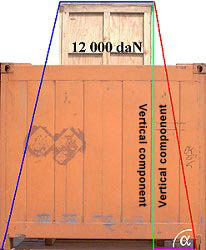
Let us assume that the wooden case on the flatrack has a weight of 12,000 daN. Without taking into account the risk of this overheight case tipping, the package must be secured for overseas shipment. Lateral acceleration forces of 0.8 g can be expected. This means that lateral forces of 12,000 daN x 0.8 or 120 kN x 0.8 i.e. 9,600 daN or 96 kN can be expected.
The single-use webbing belts used in the figure on the left have a breaking load of 3,433 daN. This equates to 2,403 daN at an MSL no greater than 70% of the breaking load. No more than half of this, i.e. around 1,200 daN, may be used as the pretensioning force. It should be noted that in practice this value can neither be achieved nor maintained throughout the entire voyage.
The effective length of the belt from its attachment to the lashing point to the edge of the case (red line) is 3.0 m. The effective height (green line) is 2.93 m, a very high vertical component (97.6%). This component can be determined for any load by dividing the effective height by the effective length. Multiplying this by the pretensioning force gives the force with which the tensioned side of the load is pulled onto the flat. In the example, this is 97.6% of 1,200 daN, or 1,171 daN. If we assume ideal conditions and this force were completely transmitted to the other side, a total pretensioning force of 2,342 daN per lashing can be assumed. Assuming a friction coefficient of 0.3, a single tie-down lashing can achieve a securing force of around 703 daN. 13.65 belts are theoretically required to secure the case (9,600 daN/703 daN). In reality, the webbing belts used would be able to maintain a maximum pretensioning force of around 100 daN through 200 daN during the voyage. This means that a single belt is able to maintain a long-term securing force of 30 daN through 60 daN. To have really "secured" the case, somewhere between 160 and 320 belts would have to be provided!!!
| Note: Tie down lashings only provide securing forces of the vertical component of the pretensioning force multiplied by the friction coefficient. |
| Note: The pretensioning force must never be greater than 50% of the MSL of the weakest securing element. |
This recipe is simpler and more precise than a calculation which uses the lashing angle α, since in practice distances are easier to measure than angles. If the vertical component of a lashing is to be calculated using the lashing angle, the permissible lashing force must be multiplied by the sine of the lashing angle: vertical component = MSL x sin α.
The smaller the lashing angle, the smaller the vertical component will be. At a lashing angle of 90° it will be 100% ( sin 90 ° = 1), at 75° 97% (sin 75 ° = 0.9659), at 60° 87 % (sin 60 ° = 0.866), at 45° 71% (sin 45 ° = 0.7071), at 30° 50% (sin 30 ° = 0.5), at 15° 26% (sin 15 ° = 0.2588) and at 0° 0% (sin 0° = 0).
Example: Direct lashing:
The main difference between direct lashings and tie-down lashings is that with direct lashings, the pretensioning force can and should be kept as low as possible.
| Note: The pretensioning force should be as low as possible on direct lashings. However, slack must never be able to develop in lashings. |
The pretensioning force must, however, be sufficiently high to prevent a lashing from becoming slack. The reason for this is that the lashing may be loaded up to its MSL under stress and the vertical components resulting from this produce additional frictional forces.
 |
Direct lashing with chains |
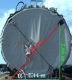
For those who enjoy mathematics, the relevant lashing forces can be calculated by first measuring the lashing angle α (47.5°) and then the sine and cosine of this angle to determine the vertical and horizontal components and using these in conjunction with the permissible lashing force of the chain.
Using another recipe, it is unnecessary to determine this angle or its sine and cosine. Basic arithmetic will suffice. The following lengths are determined by using a tape measure or meter rule: the effective length of the lashing chain (red line = 3.61 m), the effective vertical component (green line = 2.66 m) and the effective horizontal component (blue line = 2.44 m). Using rules of thumb or the manufacturer's specifications, the breaking load and the MSL of the 13 mm link material diameter high-tensile chain. This corresponds to 10,000 daN. Checking the size of the lashing point gives a steel diameter of 28.3 mm. This gives a breaking strength of 16,000 daN and an MSL of 8,000 daN. This value represents an upper threshold if the chain components have a higher MSL.
Vertical securing force: 2.66 m : 3.61 m x 10,000 daN = 7,368 daN. A lashing chain secures the package against vertical movement with a force of 7,368 daN. But this is not so important. This force becomes effective when the package is moved horizontally causing the chain to be tightened; the package is then pulled toward the floor with this force. Assuming a sliding friction coefficient of 30% (μ = 0.3), the package is secured by a lashing in all directions with a force of 7,368 daN x 0.3 = 2,210 daN.
Shortfall in securing force: 2.44 m / 3.61 m x 10,000 daN = 6,759 daN. A lashing chain directly secures the package laterally with 6,759 daN. To this are added the frictional securing forces of 2,210 daN as previously determined. The calculated chain lashing secures the machine component against movement laterally towards the right with a force of 8,969 daN.
Since no longitudinal components exist, a chain only secures the machine component longitudinally with the frictional forces produced by the vertical component of 2,210 daN.
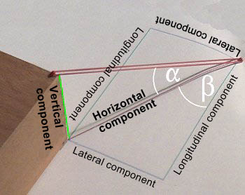 |
Different components on a diagonal lashing with lashing angles |
To calculate the longitudinal, transverse and vertical securing forces using the lashing angles α and β, use the following method:
| Component | Calculation |
| Vertical component | MSL x sin α |
| Horizontal component | MSL x cos α |
| Additional frictional forces | Vertical component x μ or MSL x sin α x μ |
| Pure lateral component | Horizontal component x sin β or MSL x cos α x sin β |
| Pure longitudinal component | Horizontal component x cos β or MSL x cos α x cos β |
Since the additional frictional forces produced by the vertical component may be added to the forces produced by the lateral and longitudinal components, the securing forces produced are:
| Securing forces | Calculation |
| Vertical securing | MSL x sin α |
| Lateral securing | MSL x cos α x sin β + MSL x sin α x μ |
| Longitudinal securing | MSL x cos α x cos β + MSL x sin α x μ |
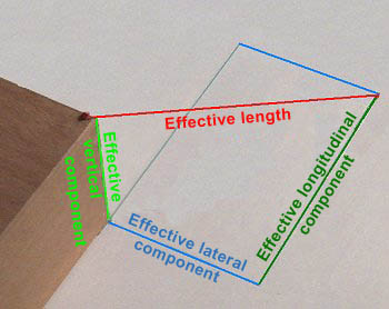 |
Determining the securing forces |
Again, a recipe is quicker, simpler and more precise. Four distances must be measured and the MSL of the weakest load securing element must be determined. The friction coefficient must be determined or estimated.
| Securing forces | Calculation |
| Vertical securing | Effective vertical component / effective length x MSL |
| Additional frictional forces | Effective vertical component / effective length x MSL x μ |
| Lateral securing including additional frictional forces | Effective lateral component / effective length x MSL + effective vertical component / effective length x MSL x μ |
| Longitudinal securing including additional frictional forces | Effective longitudinal component / effective length x MSL + effective vertical component / effective length x MSL x μ |
Calculated example:
A doubled, single-use webbing belt is used for securing as previously. For reasons of caution, the MSL is not assumed to be 70% but only 30% of the breaking load. The sketch below shows all the data needed.
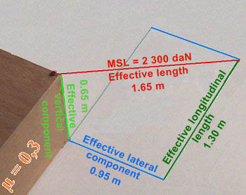 |
Calculated example: Determining the securing forces |
| Securing forces | Calculation |
| Vertical securing | 0.65 m / 1.65 m x 2,300 daN = 906 daN. |
| Additional frictional forces |
0.65 m / 1.65 m x 2,300 daN = 906 daN x 0.3 = 271.8 daN |
| Lateral securing including additional frictional forces |
0.95 m / 1.65 m x 2,300 daN = 1,324 daN + 271.8 daN = 1,595.8 daN |
| Longitudinal securing including additional frictional forces |
1.30 m / 1.65 m x 2,300 daN = 1,812 daN + 271.8 daN = 2,083.8 daN |
As far as the overall securing is concerned, it should always be borne in mind what lashings are subjected to loads under what circumstances:
 |
Package secured with four diagonal direct lashings |
| Upward | 4 x vertical securing = 4 x 906 daN | 3,624 daN |
| Longitudinally, to the left | The longitudinal components of b and c restrain | 4,167.6 daN |
| Longitudinally, to the right | The longitudinal components of a and d restrain | 4,167.6 daN |
| Laterally, upward | The lateral components of d and d restrain | 3,191.6 daN |
| Laterally, downward | The lateral components of a and b restrain | 3,191.6 daN |
It can be concluded that the lashing arrangement would not be not homogeneous if the load in the example were loaded on a flatrack transported using fore and aft stowage on a container ship, where acceleration forces of 0.4 g occur longitudinally and acceleration forces of 0.8 g occur laterally. In this instance, the lashings would need to have been arranged so that the lateral component was twice the size of the longitudinal component:
 |
Lateral components twice as large as longitudinal components |
If it is assumed that the flatrack is transported using fore and aft stowage on a container ship and transported during precarriage and/or onward carriage on a road vehicle, longitudinal and transverse acceleration forces of 0.8 g should be assumed for the lashings.
The decision in this instance is simple: both components must be the same size.
 |
Transverse and longitudinal components same size |
If the flatrack is transported during precarriage or onward transport on a freight car in multimodal operations, longitudinal acceleration forces of 1 g are assumed. If lateral acceleration forces of 0.8 g are assumed, the longitudinal components must be 25% larger than the lateral components or the lateral components can be 20% smaller than the longitudinal components:
 |
Longitudinal components 25% larger than lateral components |
Using tie-down lashings also produces angles which cause a reduction in the MSL. The effects are not very dramatic because they are the cosine of half the opening angle between the ends of the lashing. It does not really matter whether angles are measured and forces are calculated or lengths are measured. It is easier for people familiar with mathematics to calculate using the trigonometric function than to measure distances - provided a pocket calculator with trigonometric functions or a relevant table is available. Both methods are feasible. Anyone who is familiar with a the shape of a cosine wave or has certain values in their head, can also make a good estimate.
 |
Angle which is too large to be permitted |
The angle γ is 121.552°, but who can ever determine an angle as precisely as this? Half this angle is 60.776°. The cosine of this angle is 0.488. This makes it obvious that this type of securing is ineffectual. The mathematically calculated part only generates securing forces which are less than half. It would have been better to have secured the cargo with a single-strand direct lashing. The cosine of 60° is 0.5. It is therefore clear that lashings are only worthwhile if their opening angle - i.e. the complete γ - is significantly less than 120° and γ/2, significantly less than 60°. The same could have been determined - possibly more quickly - by taking measurements:
 |
As previously: Angle which is too large to be permitted |
The effective length of one end of the lashing is 197.5 cm, the effective lateral dimension is 96.5 cm. This is less than half. Both ends of the lashing together are thus less than 1. It can also be seen and proved from this that this lashing is not worthwhile.
This does not apply here:
The opening angle here is γ 27° (γ/2 is thus 13.5°). The cosine of 13.5° is 0.973 - i.e. close to 1. This means that this securing aid achieves nearly double the MSL, or to be precise 1 times the MSL of a single strand.
 |
Angle used for tie-down lashings in practice |
Measuring would have produced approximately the same results:
If - using our recipe - the smaller measured value is divided by the larger measured value, the result is 0.973. That means, the lashing secures 2 x 0.973 times, i.e. 1.946 times the MSL of a single strand.
 |
As previously: Angle used for tie-down lashings in practice |
To be precise, the angle between the ends must be measured in 3D space, since lashings which are attached to separate lashing points form an "oblique" angle to each other. These problems should not occur during measuring, even if one end comes from the top and the other end comes from the bottom.
Here are the rough guideline values for the MSL at different estimated angles:
| Estimated angle | MSL of the lashing |
| 120° | 2 x MSL of a single strand x 0.50 = 1.0 x MSL of a single strand |
| 90° | 2 x MSL of a single strand x 0.70 = 1.4 x MSL of a single strand |
| 60° | 2 x MSL of a single strand x 0.87 = 1.7 x MSL of a single strand |
| 40° | 2 x MSL of a single strand x 0.92 = 1.8 x MSL of a single strand |
| 30° | 2 x MSL of a single strand x 0.97 = 1.9 x MSL of a single strand |
| < 30° | 2 x MSL of a single strand x 1.00 = 2.0 x MSL of a single strand |