Stowage of six larger cable reels in a box container
Smallish cable reels can be secured relatively simply with a tight fit in box containers, provided the containers have an appropriate number of lashing points.
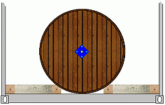 |
Bed for lateral securing of cable reels |
The cable reels are stowed with their axis lying lengthwise. Wedge members are positioned to the left and right, with flank angles which should correspond to the adjacent tangent. Unlike with steel sheet coil stowage, the cable reels lie centrally. For pressure distribution, squared lumber or planks are positioned against the container side walls. It is advisable for the appropriate lashing means to be attached before the wooden members are set in place. Special measures are not generally necessary where the lashing points are fitted between the container corrugations. If the lashing points are recessed into the container floor, the wooden members have to be recessed at these points. Between these wooden members and the wedge members, transverse members are fitted for securing purposes.
Depending on the reel packing pattern, transverse members for subsequent lengthwise securing of the reels are fitted either in front of and behind a cargo block or in front of and behind each cable reel:
| Transverse members for subsequent lengthwise securing of the cable reels | 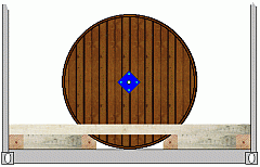 |
|
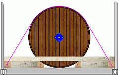 |
Overlashings preventing the reel from "popping out" of the bed under dynamic loads |
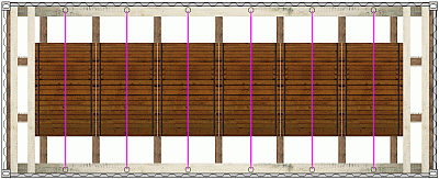
Because of the number of cable reels and lashing points, in this example the cable reels are each secured with overlashing to prevent them from "popping out" of the bed under dynamic loads. Given their function, these are not tie-down lashings but direct lashings, so that only moderate pretension may be applied.
 |
|
| Cable reels secured in all directions |
It was only possible to use one overlashing per cable reel but, nonetheless, the reels are adequately secured in the longitudinal and transverse directions, if the rolling angle remains within the usual limits for containers stowed lengthwise (fore and aft stowage).
 |
 |
|
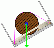
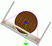
Weight-force vector at 30° rolling angle |
||
At a tilt of 30°, the weight-force vector corresponds to the line of contact with the wedge members. In this way, adequate lateral securing of the cable reels is achieved.
The picture is different if rolling angles of 45° are assumed.
 |
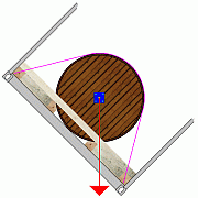 |
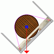
| Weight-force vector at 45° rolling angle | ||
At an inclination of 45°, the weight-force vector is outside the line of contact with the wooden wedges. In this way, adequate lateral securing of the cable reels is not achieved. They could roll out of the cradle and, to prevent this, additional lateral wooden members are required:
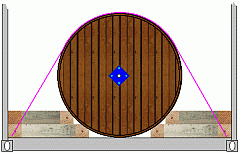 |
Additional wedge members and transverse braces for lateral securing |
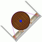
These measures allow the cable reels to be supported further up, so eliminating the risk of cargo shifting:
 |
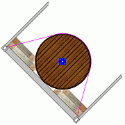 |
| Adequate securing of cable reels even in the case of a 45° rolling angle |
Even with a rolling angle of 45°, the weight-force vector is still within the line of contact with the upper wedge members.
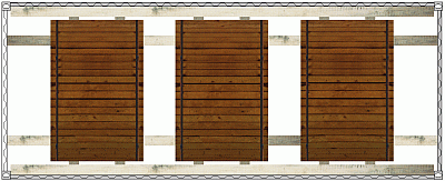
Stowage of three larger cable reels in a box container
 |
|
| Load distribution and lateral securing of the cable reels |
The cable reels are loaded uniformly in such a way that two lashing points are available on each side for each cable reel.
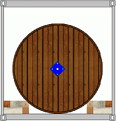 |
Lateral securing using wedge members and bracing |
To achieve better lateral securing, the wedge members were raised by placing them on other lengthwise squared lumber. In the Figure, transverse securing is effected at the level of the wedge members. It is also the intention here to secure the cable reels additionally by loop lashings through the eye loop lashings through the eye. In the case of lashing points recessed into the floor, the outer crosspieces in the bottom layer must be so positioned that the lashing points remain accessible.
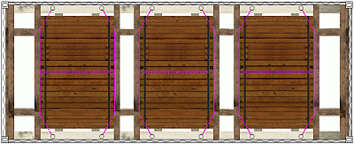 |
|
| Lengthwise securing using bracing, crosswise and vertical securing by bracing and loop lashings through the eye |
One loop lashing is positioned to the left and right through the eye of each cable reel. Together with the transversely acting wooden members, they secure the cable reels laterally and prevent them from popping out of the beds under dynamic loads. The cable reels are blocked in the lengthwise direction. At the same time, the loop lashings through the eye secure the cable reels against lengthwise tipping.
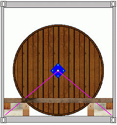 |
Securing by loop lashings and wooden bracing, in cross-section |
If lashing points are absent, additional lateral securing may be achieved by simple shoring, which is fitted between the bed lumber and the top side rail in such a way that they are retained by the container corrugations.
| Additional lateral securing by shoring | 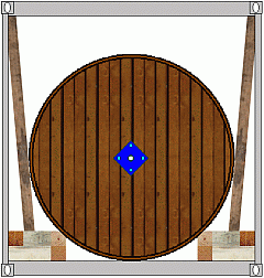 |
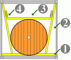
If no suitable lashing points are available in a container, lateral securing may be achieved solely by shoring. To what extent the use of wedge members or even raised wedge members is necessary depends on the particular circumstances. A simple variant is presented below, in which all that is used in the floor area is beveled crosspieces.
 |
Lateral securing by shoring - cross-section |
Each cable reel is secured in the floor area with the beveled squared lumber (1). The shoring (2) is fitted between bottom cross members and top side rails in such a way that it is stabilized by the container corrugations. Crosspieces (3) are fitted between the shoring and secured with cleats (4) in such a way that they rest on the reels.
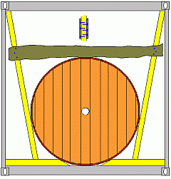
Vertical securing using boards - cross-section
Instead of squared lumber, vertical securing may also be provided by wooden dunnage boards nailed or screwed against the shoring from both sides.
 |
 |
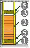 |
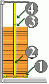
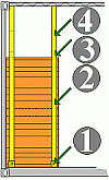
Shoring variants - side view
It depends on the dimensions and weights of the cable reels whether one shoring structure or two is provided on each side per cable reel. Sometimes additional bracing with horizontal boards (5) or even boards nailed on diagonally is necessary, to provide the shoring with a secure hold.
 |
 |
|
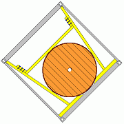
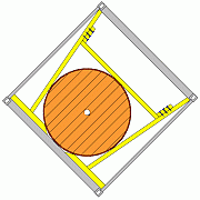
| Cable reels at a tilt of 45° | ||
However, the Figures shows clearly that it is more favorable to raise the wooden members in the floor area, since the weight-force vector is clearly outside the line of contact with the bottom cross members.