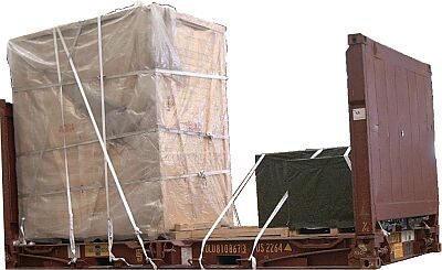
Wooden cases on a 20' flatrack, these being one overheight case and two cases of different lengths positioned next to one another
 |
|
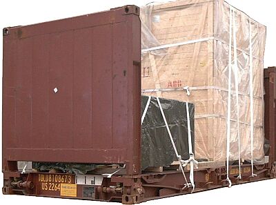
Inadequately secured cases ... from one side ... |
 |
|
| ... and from the other |
The fundamental deficiencies are:
- The inexpertly constructed wooden bracing
- The use of tie-down lashings
- The knotted webbing belts
 |
|
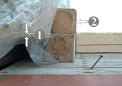
| Largely ineffective bracing |
The effective height of the squared lumber (1) is much too little to be able to provide appropriate bracing. Squared lumber (2) achieves nothing. The protruding nail is an accident waiting to happen.
 |
|
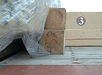
| Effective bracing |
By fitting in a further squared lumber member (3), effective lengthwise bracing can be achieved.
 |
|
| Pointless wooden member |
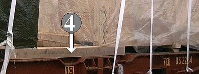
The squared lumber (4) is performing no sensible function. It is too long for building up bracing from underneath and could have been omitted.
 |
|
| Effective small area bracing |
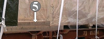
Bracing can be achieved by fitting in a wooden member (5), but the supporting surface is very small.
 |
|
| Effective bracing with appropriate pressure distribution |
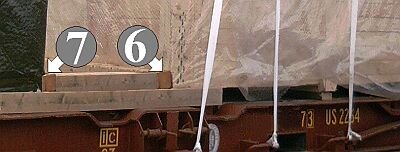
The forces arising can be distributed over a larger area by fitting crosspieces (6) (7).
 |
|
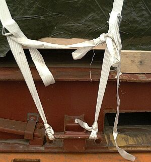
| Inadmissible use of textile webbing or belts |
Woven webbing or belts must not be knotted. They must lie flat and must not be twisted.
Correct packing and securing of the flatrack might look like this:
 |
|
| All the cases secured with a tight fit on a flatrack |
Wooden bracing (1) is prepared for the large case (b) and serves at the same time as a base for the case (a) to be loaded first. The height of the bracing must be such that the case (b) is braced at the bottom.
Two "case restraint shoes" (2) are so positioned on the flatrack that case (b) may be placed thereon with two of its transverse skids. So that the case does not sag at the bottom, the other two transverse skids are firred with boards which are as thick as the crossbars of the case restraint shoes.
Other securing methods for holding the case secure transversely at the bottom are feasible instead of the case restraint shoes, for example loop lashings. If a flatrack with stanchions was available, stanchions could also be inserted and lateral gaps between them and the case filled with lumber.
At the left-hand end of the flatrack , the case (b) is blocked with wooden bracing (3), which serves at the same time as a support for case (c), which is packed crosswise. The gap between cases (b) and (c) is braced (4).
The cases (a) and (c) are each laterally secured with 2 loop lashings (5) (6). Two steel crosspieces (7) are positioned on the top of the tall case (b), to provide lashing bars for securing the case against tipping by using two direct lashings (8) on each side.
The following Figures show details of the above arrangement:
 |
|
| Detail of the case (a) and the right-hand side of case (b) |
 |
|
| Detail of the steel crosspiece consisting of a small H-beam to which lashing stirrups with bars are welded at the sides, webbing belts being passed through the stirrups. |
 |
|
| Detail of the case (c) and the left-hand side of case (b) |
To provide more flexible cargo securing, it would be desirable if more container manufacturers would decide to affix lashing points fully capable of bearing loads over a quadrant to the insides of the end walls in the vicinity of or on the corner posts.
 |
Lashing eyes on the corner posts of a flatrack end wall |
The degree to which this extends securing options is illustrated by taking the tall case as an example.
 |
|
| Securing using direct lashings - side view |
 |
|
| Securing using direct lashings around the case - plan view |
A note of caution should be sounded here - this form of direct lashing can only produce transverse forces. It would be different if the securing materials were attached to the case corners. However, with the angles shown, transverse forces arise which are of the order of approx. 85% of the maximum securing load of the selected securing materials. In the case of single-use webbing belts with a maximum securing load of, for example, 1,000 daN per single run, transverse forces of 2 x 0.85 x 2,000 daN = 3,400 daN could be produced per "bight" if the strapping is laid double as it is here. If it is assumed that each of the four lashing points on the corner posts has a maximum securing load of 2,000 daN, transverse securing forces of 2 x 4 x 2,000 daN, i.e. 16,000 daN could be produced on each side.
 |
|
| Securing using direct lashings - plan view of two stowage variants |
The decisive factors as far as the achievable cargo securing forces are concerned are the width of the shipping packages and their distance from the end walls or their position relative to the lashing points, with the resultant angles. In the left-hand variant, transverse securing forces of approx. 80% of the maximum securing loads are achieved . To the right, the transverse securing forces amount to only 60% of the maximum securing loads due to the large distance from the end wall.