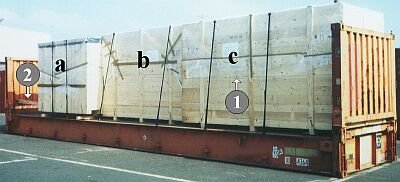
Three wooden cases on a 40' flatrack
 |
|
| Three wooden cases, secured with nothing but steel strapping tie-down lashings |
A problem with all these cases is that the side boarding ends flush with the underside of the bottom. When being picked up with forklift trucks, the boarding might be damaged by being pushed up by the channels in the fork face (see A in the Figure below):
 |
Incorrect (A) and correct (B) side boarding arrangement |
In arrangement B, the case sides end above the lower edge of the bottom by approximately their own board thickness, so meaning that the side boarding cannot be forced upwards when lifted by the forks.
The top boarding of all three cases is unfavorable, since it ends flush with the side boarding of the case (as at A). If cargo handling is not performed with frame spreader beams or spreader beams with cross beams, the vertical cable tension may pull top boards up during handling.
 |
Incorrect (A) and correct (B, C, D) top boarding arrangement |
This risk may be countered by using "heavy-lift cornerpieces" (B), lowering the top (C) or by "indenting" the top by approx. half its board thickness (D).
Another problem is that the side boarding of cases b and c is horizontal. Even small gaps between the boards considerably reduce the overall strength of the case and horizontal side boarding should only be selected if high flexural forces have to be taken up.
All three cases carry the following standard handling symbols:
- Glass, as symbol for fragile goods
- Two upright arrows, as symbol for "keep upright
- Umbrella, as symbol for "keep dry".
The slinging symbols used on all three cases are non-standard, arrows and the word UP being used instead of the standard chain symbol:
 |
 |
||
| Standard "slinging" marking |
Non-standard "slinging" marking |
The center of gravity of case c is off-center, a fact which is correctly marked at (1) with the appropriate DIN or ISO symbol.
 |
Standard symbol for center of gravity |
 |
|
| Marking of case c with regard to center of gravity and slinging (The arrows and UP have been replaced by chain symbols.) - slinging means of different lengths have to be used. |
The selected case construction and slinging point marking are completely correct, but not optimal. When the case is picked up with lifting gear, the slinging personnel must shorten the left-hand ropes so that the case hangs straight.
 |
|
| Optimized construction and marking - slinging means of the same length can be used. |
In this example, the case is constructed in such a way that the slinglift points are equidistant from the center of gravity, so meaning that ropes of the same length can be used.
As can be seen from the first picture on this page, originally, the three cases were close-packed as a block. This kind of loading makes it difficult to use different cargo securing methods. Steel strapping tie-down lashings were therefore used, together with wooden bracing (2) in the lengthwise direction.
If loading is modified, other cargo securing methods can be used.
In this example, the cases are spaced out and again secured in the lengthwise direction by wooden bracing:
 |
|
| Spaced cases, cases secured lengthwise by bracing the gaps - side view |
 |
|
| Spaced cases, cases secured lengthwise by bracing the gaps - plan view |
The following Figures give a better view of the details:
 |
 |
|
| Details of bracing - side and plan view | ||
The squared lumber (1) is laid lengthwise, at a distance from the corners which corresponds to approx. a quarter of the case width. The wooden members (2) are laid crosswise thereon. The pairs of wooden members (1) and (2) match the height between the bottom edge of the case bottom and the flatrack floor. Boards or squared lumber are positioned on the wooden members (2) to the left and right of the gap against the cases or against a case and a flatrack end wall (3) to distribute pressure. The squared lumber (4) is inserted between these wooden members for lengthwise bracing.
The cases are secured laterally by loop lashings, while securing against tipping is provided by tie-down lashings. For overall securing of the three cases, a total of four bracing members, six loop lashings and six tie-down lashings are required. The following two Figures show an overview of the securing arrangements and a detail thereof:
 |
|
| Overall securing of the cases: Lengthwise securing using bracing (1). Transverse securing in each case using two loop lashings (2) and (3) and securing against tipping provided by in each case two tie-down lashings (4) |
 |
|
| Case securing detail: Lengthwise by bracing (1) against the flatrack end wall and the adjacent case, crosswise by in each case two loop lashings (2) and (3) and against tipping by in each case two tie-down lashings (4) |
The three cases could be secured somewhat more cheaply if a flatrack with stanchions were used. The cases would be arranged differently on the flatrack, with the widest case (a) arranged in the middle and cases (b) and (c) positioned in the vicinity of the end walls, in such a way that they are secured crosswise in each case by two pairs of stanchions, case (c) being secured by stanchion pairs (1)/(2) and (3)/(4) and case (b) by stanchion pairs (5)/(6) and (7)/(8). The gaps are filled with bracing (9), (10), (11) and (12). No stanchions are used for case (a) because of its width; instead, it is secured crosswise by the two loop lashings (d) and (e). Each of the three cases is secured against tipping by two tie-down lashings (f).
 |
|
| Securing of three cases on a flatrack with stanchions |
To make the cargo securing clearer, the securing arrangements used here for each case are shown in detail.
 |
|
| Securing of the centrally positioned case (a) |
The crimson-colored loop lashing (d) extends at the level of the center of gravity of the case from stanchion(4) around the outside of the case to stanchion (6). The bluish-purple loop lashing (e) is likewise passed at the level of the center of gravity of the case from stanchion (3) around the outside of the case to stanchion (5).
 |
|
| Securing of case (b) positioned in vicinity of end wall |
 |
|
| Securing of case (c) positioned in vicinity of end wall |
The wooden members used for bracing must be attached in such a way as to make slippage impossible. If necessary, they should be X-braced. The tie-down lashings should be positioned as far as possible equidistantly from the center of gravity of the case. When using steel strapping, the tie-down lashings should be passed over edge protectors with good recovery. Very favorable securing options would be achieved if special flatracks with clamping jaws were available for transporting large cases and similar shipping packages.
 |
Flatrack with clamping jaws |
 |
|
| Securing a case with spindle-guided clamping jaws (1) and tie-down lashings (2) |
 |
|
| Detail of securing using clamping jaws |
The clamping jaws must be ridged or spiked, to achieve a tight fit in the lengthwise direction by penetrating into the outside of the case. The availability of such flatracks would simplify cargo securing enormously. If the cases were expertly constructed, it would at any rate be possible to dispense with any further lengthwise and transverse securing. If conditions were particularly favorable, it would even be possible to do without tie-down lashings.