 |
|
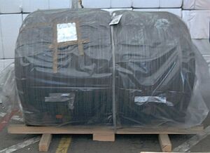
| Shortcomings in packaging a wire rod coil |
The base of the wire coil protrudes and thus complicates loading and securing. Including lumber components in the plastic wrapping increases the risk of corrosion as condensation can form under the covering.
 |
|
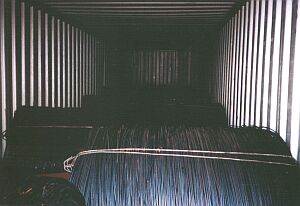
| Inadequate stowage and securing of wire rod coils |
The wire rod coils have simply been set down alternately against the container side walls. Sheets of cardboard have been inserted at the contact points between the coils.
 |
|
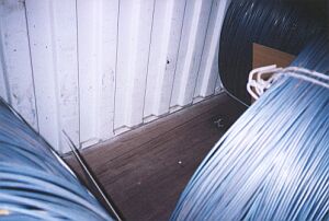
| View into a container with wire rod coils |
The wire rod coils are in direct contact with the container side walls. This may result in chafing of the container side walls. The wire rod could then suffer corrosion if water vapor from the cardboard, the container floor and similar sources were to condense in relatively large quantities on the container roof and walls and be able to wet the wire rod coils.
 |
|
| Gaps in a container packed with wire rod coils |
The gaps in the container cargo would only present no risk if the wire coils were 100% solidly intermeshed.
 |
|
 |
|
| Compact, intermeshed stowage - lengthwise gaps filled |
This may be an acceptable loading method not entailing major securing effort if dimensions permit extremely compact packing and the wire coils are able to intermesh effectively without resulting in damage to the goods. In the example shown in the diagram, the gap between the front end wall and the inner edge of the corner post is filled with a wooden lattice (a) of horizontal and vertical boards, onto which a board is nailed horizontally at winding axis height. The coils are arranged on alternate sides and tightly pressed towards the front end wall. Once the left door leaf had been closed, the remaining gap was filled with a lattice (b) of boards and a squared lumber member at winding axis height.
 |
Wedge with handle for restraining wire coils |
To stop the preceding coil from "slackening" before the next one is loaded, the first one can be held in its initially loaded position using a wedge with a handle.
 |
|
| Wire rod coils packed with winding axis crosswise - secured with wooden bracing |
Provided that there is no risk of corrosion or kiln dry lumber is used, the wire rod coils could be secured as shown here in the diagram.
The coils could each be secured in the lengthwise direction with wedges. In this example, however, in order to prevent wetting damage, it is important to place as little kiln dry lumber in the container as possible.
 |
|
| Preparation of wooden bracing |
Short squared lumber members (a) and two boards (b) and (c) are nailed together. The short squared lumber members should be of dimensions such that they exactly fit into the wire rod coil eye. The boards (b) and (c) overlap one another in steps. Two further boards (d) and (e) are joined together in the same manner. Between these pairs of boards are fitted two squared lumber members (g) which are dimensioned such that, together with the thickness of the four boards, they fill the gap in the load. These bracing structures are located with the squared lumber members (a) in the eyes of the wire coils in such a manner that the boards (d) and (e) rest against the container walls. They are prevented from slipping down by inserting oblique boards (f).
 |
Bracing fitted into the eye of a wire coil |
 |
 |
|
| Section through the container | Plan view of two wire coils |
Assuming a coefficient of sliding friction of μ = 0.2 and transport acceleration values of 0.8 g in the sideways direction, the container's full payload can be utilized as the container side walls are capable of withstanding 0.6 times the payload uniformly applied. It is, however, recommended that strips of friction-enhancing material be laid under the wire rod coils.
Since the wire coils are able to roll in the lengthwise direction of the container, no coefficients of sliding friction need be assumed for the lengthwise direction. Compact packing in the lengthwise direction is only adequate if (due to the loading capacity of the container end walls of 0.4 times the payload) the acceleration values anticipated during shipping do not exceed 0.4 g. If higher levels of acceleration are anticipated, the wire coils should be secured in the lengthwise direction with additional wedges or wedge beams which are capable of absorbing a proportion of the forces.